


.jpg)
 EDGECAM Milling
Gia công thông minh từ Native CAD Data
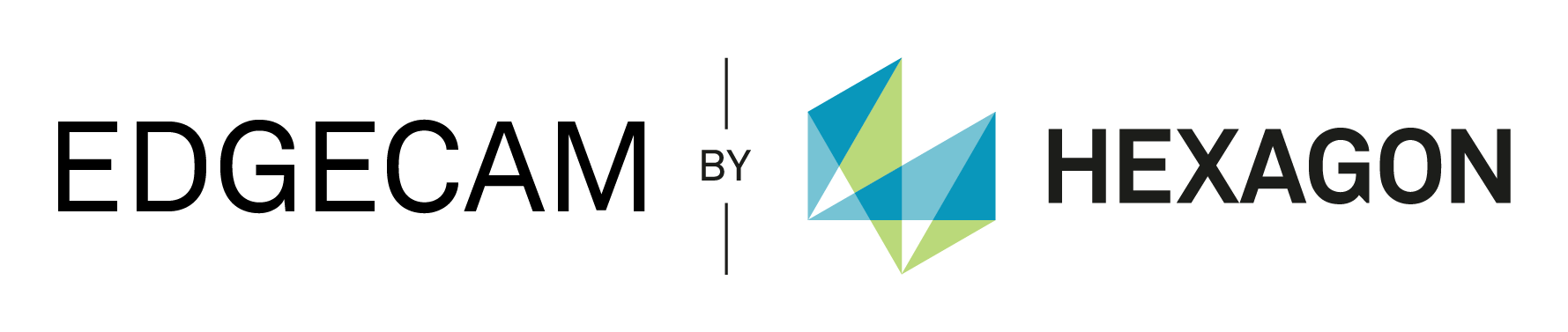
Phay EDGECAM cung cấp chức năng lập trình hình học khung dây hoặc các chi tiết mô hình khối trên nhiều cấu hình máy công cụ, từ phay 2.5 trục đến các đường chạy dao gia công bề mặt phức tạp trên máy phay 3-5 trục.
EDGECAM tích hợp liền mạch gia công đồng thời 4 và 5 trục trong phạm vi môi trường phay và phay/tiện của nó, cho phép áp dụng một loạt các chiến lược cắt đa trục đối với các thành phần và công cụ phức tạp nhất.
EDGECAM mang lại sự tương tác trực quan giúp người dùng dễ dàng lập trình hơn, ngoài ra phần mềm còn có khả năng kiểm soát thông minh đường chạy dao cho các yêu cầu nâng cao.
Lướt qua các tính năng:
|
|
Find out more
The ability to use Solid models and the design data from all the major CAD system maintaining associative links allows quick and efficient programming, especially when a Design modification is made. EDGECAM will inform the user of model updates and show what the changes are and where tool paths need to be corrected. A simple update of the tool paths is all that is required rather than a reprogram of the part. Tombstone and multi part fixture is supported, along with extended datum shifts.
EDGECAM offers ease of use operational programming with intuitive dialogues making programming simple for the new user and comprehensive tool path control for the more advanced requirements. EDGECAM offers range of milling commands for the production engineer which can be used on both milling machines with W axis and Quills plus lathes with driven tools with . Face Milling, Roughing, Profiling, Hole Cycles, Thread Milling, Chamfering, Slot Milling are some of the standard operations available and recognise the active stock
Update stock. Tool paths can be controlled using the current stock which ensures tool path approach is secure and eliminates fresh air cutting. The stock can originate from automatically created stock or from a forging or casting model produced in CAD.
Face Milling Creates a series of straight cuts on a horizontal plane. Face milling will recognise the boundary shape and remove air cuts where applicable, links moves for change in cut direction can be controlled to give smooth transition producing and even flow tool path which is kinder to the machine tool and cutter engagement.
Hole Cycles EDGECAM includes all the standard drilling, tapping and rigid tapping routines with canned cycle and sub routine output. Back boring is also available where conventional machining cannot be achieved on the part. When using solid models the hole size , thread data, depths etc is extracted and the necessary tooling suggested from the tool libraries.
Rough Milling Has a variety of tool path control and methods, from lace, concentric, spiral and the wave form tool path. EDGECAM produces the required tool path and tool entry into the material. Shape recognition allows sub routines to be applied with a simple check box. EDGECAM will recognise the change in geometry walls and create sub routines as appropriate.
Waveform Roughing Waveform cycle is superior to the traditional roughing cycle where machinable geometry is offset inward or outward by % step over. TRADITIONAL tool paths have to run slower feeds and speeds due to the variable widths of cut condition when encountering corners and material entry.
Wave form toolpath has been developed to remove tool load spikes and maintain and even chip thickness and generating a fluid tool path throughout the machinable elements using a flowing motion. Consistent tool loads generated from the waveform tool path offers the user the opportunity to rethink speeds, feeds and depths of cut. The Waveform tool path increases tool life and is also kinder to the machine tool.
Thread Milling Thread milling is a popular technique when machining threaded holes on larger components, especially in the oil and gas, power generation and other heavy industries. EDGECAM’s thread milling cycle will automatically suggest entry points, and lead in lead out paths. Single pass or mutli-pass helical move tool paths can be output.
Automation Strategy Manager Automation is a flow chart decision making process using to your manufacturing methods/ knowledge. EDGECAM recognises manufacturing features and data from a 3D solid model and applies your proven manufacturing tool paths and techniques. This creates tool path cycles automatically with your own tooling to your requirements. This greatly reduces the offline programming time maximising on your investment plus aids learning curves for new engineers.
Probing EDGECAM supports Renishaw probing part setup cycles. The probing cycles can be integrated by simply adding an additional toolbar to the user interface. This supports all datum offset part positional requirements which can be a pre-requisite to actual machining whether on 3 axis mill or multi-pallet tombstone fixture.
Indexing and Part Positioning Support for single or compound indexing with a using A, B or C axis combination using safety clearance zones to give 4 or 5 axis positioning. Datum shifting and extended offsets can be output for each new position.
Angle Heads Support for Angled Head attachments is available in EDGECAM. The holder and tool can be saved in the comprehensive tool libraries and called up in the tool change along with material feeds and speeds. The use of angle heads will use plane switching if supported by the machine tool control. When used, the holder body along with the tool is collision check in the machine simulator.
Shop Floor Documentation Documentation of the operation process is automatically created along with tooling kit/list, operation breakdown and can be stored centrally on a server so all production staff can access the data. Machine tool set up information along with digital images can also be added along with stock and fixture requirements. Documents and pre set tool drawing can be attached. This module is standard with all systems and is very useful solution for pre setting tooling areas.
EDGECAM has now made this easier to use with the operational style interface yet still have all the control required for the higher demands such as :
- SWARF cutting for machining of variable taper walls.
- 5 axis finishing across multiple surfaces with control over lead/lag and side tilt angles 5 axis profile machining for slotting, de-flashing and trimming of sheet forms.
- Full support for all common tool profiles, including lollipopcutters.
- Easy-to-use machining strategies are geared to maximize productivity and quality.
Introduction to 5 Axis is made easier with the 3 to 5 axis tool conversion and the peace of mind that the program is correct using the machine tool simulator.
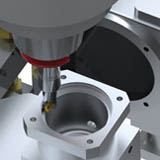
EDGECAM’s 4 axis strategies are ideal for the rotary machining of automotive and aerospace components such as camshafts, crankshafts and blades, as well as the production of rotary dies and components for the oil & gas industry.
4 and 5 axis simultaneous machining offer key advantages over conventional indexed 3-Axis machining:
- Reduced cycle time by machining complex components in a single setup. In addition, dimensional accuracy can be significantly improved through the elimination of positioning errors between setups.
- Improved surface finish and extended tool life are achieved by orienting the tool to maintain optimum tool to-part contact at all times.
- Improved access to undercuts and deep pockets - through tilting the tool or component allows shorter series tooling to be employed, eliminating the
need for secondary setups. - Reduced fixturing, as the cutter can be presented to the component at any
required angle.
5 axis machining is now common place in all areas of manufacturing as high technology machines have become more affordable along with design demands requiring more complicated tool paths.
3 to 5 axis Tool Path Conversion. Using the knowledge of 3 axis machining methods, the standard EDGECAM milling cycles and operations can be used on a component then apply the 5 axis tool path conversion. This produce 5 axis movement where required, ensure tool lengths are kept to a minimum and the cutting tool and holder tilted away from the component avoiding any collision. This methodology is an easy way to move into 5 axis programming technology.
Turn Milling. Use the 4th axis rotary attachment on the milling machine to produce a turned shaft using milling cutters rather than using a lathe for a partial operation. This process relies on the percentage engagement of the milling cutter while rotating the component which is made simple using EDGECAM. The same principal is also used to produce cam forms. Five Axis Finishing Five axis finishing across multiple faces is similar to a parallel lace or scanning tool path but controls the tilt relative the surface which is driving the cycle.
SWARF Milling Side Wall Axial Relief Feed. This is common practice when driving the side of the tool along a surface which tilts from side to side, this is in common practice on many aerospace parts. The tilt is control by the surface wall and the tool lift controlled by the base surface or bounding curve.
5 axis Positioning. 5 axis machines are also capable of 5 axis positioning, also called 3+2. This is where the component can be positioned using a combination of 3 axis linear movement with 2 axis rotary movement. A standard 3 Axis machining method can then be applied on to the component face orientated towards the spindle. These tool paths may also have the 3 to 5 axis conversion applied.
Tool Path Control. 5 axis tool paths can result in large movements of the machine tool from what can be a very small cut on the component. These movements can cause severe damage the part and machine. EDGECAM provides methods for collision avoidance where the cutter and holder are checked for collision and the necessary tilts applied to move away from the potential collision area.Inverse Time Feed is control implemented to ensure the feed rate at the cutting tip is does not slow or dwell when small movements of the cutter produces a large movement of the machine tool. Inverse time feed allows a specified distance to move the tool during a specified time, this ensures the tool tip motion is correct and the machine tool movement will compensation to suit.